npm install --unsafe-perm --verbose -g sails
這一行指令對 raspberry pi 安裝nodejs 很重要
Node.js Raspberry Pi - GPIO Introduction
What is GPIO?
GPIO stands for General Purpose Input Output.
The Raspberry Pi has two rows of GPIO pins, which are connections between the Raspberry Pi, and the real world.
Output pins are like switches that the Raspberry Pi can turn on or off (like turning on/off a LED light). But it can also send a signal to another device.
Input pins are like switches that you can turn on or off from the outside world (like a on/off light switch). But it can also be a data from a sensor, or a signal from another device.
That means that you can interact with the real world, and control devices and electronics using the Raspberry PI and its GPIO pins!
Taking a Closer Look at the GPIO Pins
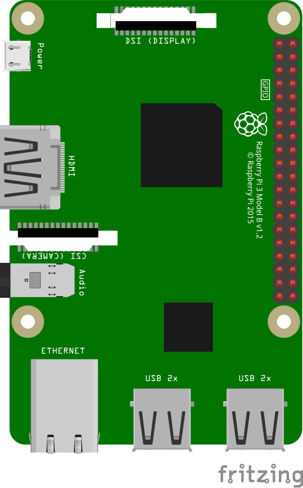
This is an illustration of the Raspberry Pi 3.
The GPIO pins are the small red squares in two rows on the right side of the Raspberry Pi, on the actual Raspberry Pi they are small metal pins.
The Raspberry Pi 3 has 26 GPIO pins, the rest of the pins are power, ground or "other".
The pin placements correspond with the table below.
Raspberry Pi B+, 2, 3 & Zero
| 3V3 | 1 | 2 | 5V |
| GPIO 2 | 3 | 4 | 5V |
| GPIO 3 | 5 | 6 | GND |
| GPIO 4 | 7 | 8 | GPIO 14 |
| GND | 9 | 10 | GPIO 15 |
| GPIO 17 | 11 | 12 | GPIO 18 |
| GPIO 27 | 13 | 14 | GND |
| GPIO 22 | 15 | 16 | GPIO 23 |
| 3V3 | 17 | 18 | GPIO 24 |
| GPIO 10 | 19 | 20 | GND |
| GPIO 9 | 21 | 22 | GPIO 25 |
| GPIO 11 | 23 | 24 | GPIO 8 |
| GND | 25 | 26 | GPIO 7 |
| DNC | 27 | 28 | DNC |
| GPIO 5 | 29 | 30 | GND |
| GPIO 6 | 31 | 32 | GPIO 12 |
| GPIO 13 | 33 | 34 | GND |
| GPIO 19 | 35 | 36 | GPIO 16 |
| GPIO 26 | 37 | 38 | GPIO 20 |
| GND | 39 | 40 | GPIO 21 |
Legend
| Physical Pin Number |
| Power + |
| Ground |
| UART |
| I2C |
| SPI |
| GPIO |
| Do Not Connect |
Taking a Closer Look at the Breadboard
A breadboard is used for prototyping electronics, it allows you to create circuits without soldering. It is basically a plastic board, with a grid of tie-points (holes). Inside the board there are metal strips connecting the different tie-points in specific ways.
In the illustration below we have highlighted some of the sections with different colors. This is to show you how the grid is connected.
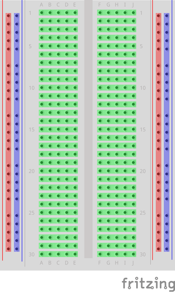
The different sections of the breadboard:
- On the left, and right, side there are 2 columns of tie-points. All the tie points in each of these columns are connected.
- The Power Bus - The columns highlighted with red. There are usually used to connect power to the Breadboard. Since the entire column is connected, you can connect power to any of the tie-points in the column.
- The Ground Bus - The columns highlighted with blue. There are usually used to connect Ground to the Breadboard. Since the entire column is connected, you can connect ground to any of the tie-points in the column.
- Rows of connected Tie-Points - The rows highlighted with green. The tie-points of each of these rows are connected, but not the entire row! The left side tie-points are connected (A-B-C-D-E), and the right side tie-points are connected (F-G-H-I-J).
- In the center of the Breadboard there is a Trench, this separates the left and right rows. The width of the trench is designed so that many Integrated Circuits fit across it.
Install the onoff Module
To interface with the GPIO on the Raspberry Pi using Node.js, we will use a Module called "onoff".
Install the onoff module using npm:
pi@w3demopi:~ $ npm install onoff
Now onoff should be installed and we can interact with the GPIO of the Raspberry Pi.
Using the GPIO for Output
In this chapter we will use a Raspberry Pi and its GPIO to make a LED blink.
We use Node.js with the onoff module to control the GPIO.
To get a LED light to turn on, we use a GPIO pin as "Output", and create a script to turn it on and off (blinking).
What do we need?
In this chapter we will create a simple example where we control a LED light.
For this you need:
- A Raspberry Pi with Raspian, internet, SSH, with Node.js installed
- The onoff module for Node.js
- 1 x Breadboard
- 1 x 68 Ohm resistor
- 1 x Through Hole LED
- 2 x Female to male jumper wires
Click the links in the list above for descriptions of the different components.
Note: The resistor you need can be different from what we use depending on the type of LED you use. Most small LEDs only need a small resistor, around 200-500 ohms. It is generally not critical what exact value you use, but the smaller the value of the resistor, the brighter the LED will shine.
Building the Circuit
Now it is time to build the circuit on our Breadboard.
If you are new to electronics, we recommend you turn off the power for the Raspberry Pi. And use an anti-static mat or a grounding strap to avoid damaging it.
Shut down the Raspberry Pi properly with the command:
pi@w3demopi:~ $ sudo shutdown -h now
After the LEDs stop blinking on the Raspberry Pi, then pull out the power plug from the Raspberry Pi (or turn of the power strip it is connected to).
Just pulling the plug without shutting down properly may cause corruption of the memory card.
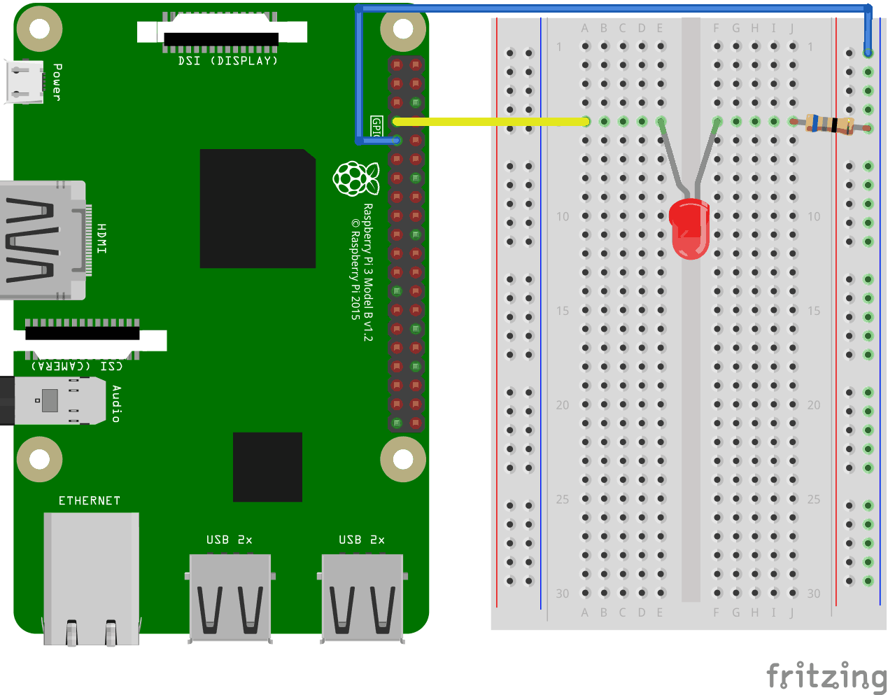
Look at the above illustration of the circuit.
- On the Raspberry Pi, connect the female leg of the first jumper wire to Ground. You can use any GNDpin. In this example we used Physical Pin 9 (GND, row 5, left column)
- On the Breadboard, connect the male leg of the first jumper wire to the Ground Bus column on the right. That entire column of your breadboard is connected, so it doesn't matter which row. In this example we have attached it to row 1
- On the Raspberry Pi, connect the female leg of the second jumper cable to a GPIO pin. In this example we used Physical Pin 7 (GPIO 4, row 4, left column)
- On the Breadboard, connect the male leg of the second jumper wire to the Tie-Point row of your choice. In this example we connected it to row 5, column A
- On the Breadboard, connect one leg of the resistor to the Ground Bus column on the right side. That entire column of your breadboard is connected, so it doesn't matter which row. In this example we have attached it to row 5
- On the Breadboard, connect the other leg of the resistor to the right side Tie-Point row of your choice. In this example we have used row 5, column J
- On the Breadboard, connect the cathode leg (the shortest leg) of the LED to the same Tie-Point row that you connected the resistor from GND to. In this example we used row 5, column F
- On the Breadboard, connect the anode leg (the longest leg) of the LED to the same Tie-Point row that you connected the jumper from the GPIO pin to. In this example we used row 5, column E
Your circuit should now be complete, and your connections should look pretty similar to the illustration above.
Now it is time to boot up the Raspberry Pi, and write the Node.js script to interact with it.
Raspberry Pi and Node.js Blinking LED Script
Now that we have everything set up, we can write a script to turn the LED on and off.
Start by making a directory where we can keep our Node.js scripts:
pi@w3demopi:~ $ mkdir nodetest
Go to our new directory:
pi@w3demopi:~ $ cd nodetest
Now we will create a new file called "
blink.js" using the Nano Editor:
pi@w3demopi:~ $ nano blink.js
The file is now open and can be edited with the built in Nano Editor.
Write, or paste the following code:
blink.js
var Gpio = require('onoff').Gpio; //include onoff to interact with the GPIOvar LED = new Gpio(4, 'out'); //use GPIO pin 4, and specify that it is outputvar blinkInterval = setInterval(blinkLED, 250); //run the blinkLED function every 250ms
function blinkLED() { //function to start blinking if (LED.readSync() === 0) { //check the pin state, if the state is 0 (or off) LED.writeSync(1); //set pin state to 1 (turn LED on) } else {
LED.writeSync(0); //set pin state to 0 (turn LED off) }
}
function endBlink() { //function to stop blinking clearInterval(blinkInterval); // Stop blink intervals LED.writeSync(0); // Turn LED off LED.unexport(); // Unexport GPIO to free resources}
setTimeout(endBlink, 5000); //stop blinking after 5 seconds
Press "
Ctrl+x" to save the code. Confirm with "y", and confirm the name with "Enter".
Run the code:
pi@w3demopi:~ $ node blink.js
Now the LED should blink for 5 seconds (10 times) before turning off again!
留言
張貼留言